Debian 12
For development, it is recommended to work directly in Debian on the SD
card. Debian provides many more packages and a much more familiar
environment for users already versed in Debian. Through Debian it is
possible to configure the network, use the apt-get suite to manage
packages, and perform other configuration tasks. Out of the box the
Debian distribution does not have any default username/password set.
The account root is set up with no password configured. It is possible
to log in via the serial console without a password but many services
such as ssh will require a password set or will not allow root login at
all. It is advised to set a root password and create a user account when
the unit is first booted.
Setting up a password for root is only feasible on the uSD image.
It is also possible to cross compile applications. Using a Debian host system will allow for installing a cross compiler to build applications. The advantage of using a Debian host system comes from compiling against libraries. Debian cross platform support allows one to install the necessary development libraries on the host, building the application on the host, and simply installing the runtime libraries on the target device. The library versions will be the same and completely compatible with each other. See the respective Debian cross compiling section for more information.
Getting Started With Debian
This Debian release is available in 2 flavors with various packages. See our Debian releases in the Software Images section for links to the latest images available.
| Image | Description |
|---|---|
| Headless |
|
| Minimal |
|
The default login is root with no password.
Configuring the Network
The network in Debian is configured with /etc/network/interfaces. For complete documentation, see Debian's documentation here
Some common examples are shown below. On this release network interfaces follow the predictable network interface names. Run ip addr show to get a list of the network interfaces.
Most commonly:
end0 - Ethernet device 0 (CPU Ethernet)
enp1s0 - Ethernet PCIe port 1 slot 0 Ethernet
usb<mac> - USB Ethernet
wlan0 - Wi-Fi
DHCP on end0. Create the file /etc/network/interfaces.d/end0 with the contents:
allow-hotplug end0
iface end0 inet dhcp
Static IP on end0. Create the file /etc/network/interfaces.d/end0 with the contents:
allow-hotplug end0
iface end0 inet static
    address 192.0.2.7/24
    gateway 192.0.2.254
These will take effect on the next boot, or by restarting the networking service:
service networking restart
Wi-Fi Client
Wireless interfaces are also managed with configuration files in /etc/network/interfaces.d/. For example, to connect as a client to a WPA network with DHCP. Note some or all of this software may already be installed on the target.
Install wpa_supplicant:
apt-get update && apt-get install wpasupplicant -y
Run:
wpa_passphrase youressid yourpassword
This command will output information similar to:
network={
  	ssid="youressid"
  	#psk="yourpassword"
	psk=151790fab3bf3a1751a269618491b54984e192aa19319fc667397d45ec8dee5b
}
Use the hashed PSK in the specific network interfaces file for added security. Create the file /etc/network/interfaces.d/wlan0 with the contents:
allow-hotplug wlan0
iface wlan0 inet dhcp
    wpa-ssid youressid
    wpa-psk 151790fab3bf3a1751a269618491b54984e192aa19319fc667397d45ec8dee5b
To have this take effect immediately:
service networking restart
For more information on configuring Wi-Fi, see Debian's guide here.
Host a Wi-Fi Access Point
The latest image for this platform as of April 28th, 2022 has known issues with the Wi-Fi driver due to incompatibility with cfg80211 powersave modes.
If using Wi-Fi, it is strongly recommended to bring up the Wi-Fi interface, and then run iw wlan0 set power_save off to disable powersave modes.
This issue will be addressed in future images and has already been addressed in our kernel sources. We will continue to provide updates as we receive them from the Wi-Fi module manufacturer.
This section will discuss setting up the WiFi device as an access point that is bridged to an ethernet port. That is, clients can connect to the AP and will be connected to the ethernet network through this network bridge. The ethernet network must provide a DHCP server; this will be passed through the bridge to WiFi client devices as they connect.
It is also possible to run a DHCP client on the platform itself. In this
case the hostapd.conf file needs to be set up without bridging and a
DHCP server needs to be configured. Refer to
Debian's documentation for more details on DHCP
server configuration.
The 'hostapd' utility is used to manage the access point of the device. This is usually installed by default, but can be installed with:
apt-get update && apt-get install hostapd -y
The install process may start an unconfigured 'hostapd' process.
This process must be killed before moving forward.
Modify the file /etc/hostapd/hostapd.conf to have the following
lines:
ssid=YourWiFiName
wpa_passphrase=Somepassphrase
interface=wlan0
channel=7
driver=nl80211
logger_stdout=-1
logger_stdout_level=2
wpa=2
wpa_key_mgmt=WPA-PSK
Refer to the kernel's hostapd documentation for more wireless configuration options.
The access point can be started and tested by hand:
hostapd /etc/hostapd/hostapd.conf
Systemd auto-start with bridge to eth0
It is possible to configure the auto-start of hostapd through
systemd. The configuration outlined below will set up a bridge with
eth0, meaning the Wi-Fi connection is directly connected to the
ethernet network. The ethernet network is required to have a DHCP server
present and active on it to assign Wi-Fi clients an IP address. This
setup will allow Wi-Fi clients access to the same network as the
ethernet port, and the bridge interface will allow the platform itself
to access the network.
Set up hostapd
First, modify the hostapd configuration to understand the bridge interface:
echo "bridge=br0" >> /etc/hostapd/hostapd.conf
Create the file /etc/systemd/system/hostapd_user.service with the
following contents:
[Unit]
Description=Hostapd IEEE 802.11 AP
Wants=network.target
Before=network.target
Before=network.service
After=sys-subsystem-net-devices-wlan0.device
After=sys-subsystem-net-devices-br0.device
BindsTo=sys-subsystem-net-devices-wlan0.device
BindsTo=sys-subsystem-net-devices-br0.device

[Service]
Type=forking
PIDFile=/run/hostapd.pid
ExecStart=/usr/sbin/hostapd /etc/hostapd/hostapd.conf -P /run/hostapd.pid -B

[Install]
WantedBy=multi-user.target
Then enable this in systemd:
systemctl enable hostapd_user.service
systemctl enable systemd-networkd
Set up bridging
Create the following files with the listed contents.
/etc/systemd/network/br0.netdev
[NetDev]
Name=br0
Kind=bridge
/etc/systemd/network/br0.network
[Match]
Name=br0

[Network]
DHCP=yes
/etc/systemd/network/bridge.network
[Match]
Name=eth0

[Network]
Bridge=br0
Wi-Fi Concurrent Client / Access Point
Configure the WiFi as an access point as above
The channel used for AP must match the channel the STA is using! Be sure to set channel=\... in the above file to a proper channel number.
In order for the concurrent modes to work, a separate virtual wireless device must first be created.
Note that hostapd.conf above lists interface=p2p0, a second interface with this name must be
created:
iw wlan0 interface add p2p0 type managed
The access point can then be started and tested by hand:
hostapd /etc/hostapd/hostapd.conf &
An IP address can be set to p2p0:
ifconfig p2p0 192.168.0.1
From this point, other Wi-Fi clients can connect to the SSID
YourWiFiName with the WPA2 key Somepassphrase with a
static IP in the range of 192.168.0.0/24, and will be able to access the platform at
192.168.0.1
More advanced configurations are also possible, including bridging, routing/NAT, or simply separate networks with the Wi-Fi module connecting to a network and hosting its own private network with DHCP.
Cellular Data Network
DC-TS767-MT MultiTech Modem
The board includes support for the Multitech MTSMC-G2 or MTSMC-H5 connected via the TS-DC767-MT daughter card, which can connect to the internet using pppd. The modem is attached to the HD1 Header, also called the Daughter Card interface. The modem itself can be configured with the following commands:
ln -s /dev/ttymxc6 /dev/ttymultidc
There are two GPIO pins that can control reset and RTS of the cell modem. These two pins default to an I2C mode, so before they can be used, they must have the pinmux set to GPIO. This can be done with the following two commands:
peekpoke 32 0x20e0118 0x5  #Set RTS pin to GPIO, GPIO 69
peekpoke 32 0x20e011c 0x5  #Set reset pin to GPIO, GPIO 70
The DIO pins can be controlled now from the linux GPIO subsystem. In order to function properly, the RTS pin must be low, and the reset must be high. This can be done with the following commands:
gpioset gpiochip1 9=0
gpioset gpiochip2 17=0
The pppd application must be installed and any required modules loaded:
apt-get update && apt-get install -y ppp
This example is configured for T-Mobile in the US:
/dev/ttymultidc
noauth
115200
debug
usepeerdns
persist
defaultroute

connect "/usr/sbin/chat -v -f /etc/ppp/chatscripts/tmobile"
disconnect "/usr/sbin/chat -v -f /etc/ppp/chatscripts/tmobile-disconnect"
TIMEOUT 10
ABORT 'BUSY'
ABORT 'NO ANSWER'
ABORT 'ERROR'

"" "\p\p\p\p\p\p\p\p\p\p\p\p+++\p\p\p\p\p\p\p\p\p\p\p\p"
"" "ATH0"

"OK" 'AT+CGDCONT=1,"IP","wap.voicestream.com"'

ABORT 'NO CARRIER'
OK 'ATD*99***1#'
CONNECT
"" "\K"
"" "+++ATH0"
Using a different carrier you will likely only need to replace
wap.voicestream.com with the access point for your carrier.
To start pppd:
pppd call tmobile

# Or for more logging information:
# pppd nodetach call tmobile
This will create a ppp0 interface that can now be used as a standard network interface, and should set up a default route to the internet. For other carriers, typically you will only need a different access point listed in the AT+CGDCONT call, but further adjustments may be necessary.
We have observed that the MTSMC-H5 connected to some networks has issues at or below 115200 baud. The issues observed are connection timeouts with the network itself. The connection between the modem and host device remain rock solid. While many applications are tolerant to the connection being reset, we have found some network downloads will abort without being able to recover. Running the unit at a faster baud rate, 230400 or higher, has been observed to eliminate this issue entirely. This does mean, however, that every time the device is started up, the modem must be issued an AT+IPR command (as noted below) at 115200 baud, then pppd started with the matched and higher baud rate in the peer script as shown above.
Faster Data Rates
While the MTSMC-G2 (GPRS) is limited to 115200 baud, the MTSMC-H5 (HDSPA) can communicate over serial up to 921600 allowing actual transfer rates around 80-90KB/s.
To set a custom baudrate in Linux, the method depends on the CPU and
kernel support. More recent UART peripherals have a higher clock and a
smarter driver, and can therefore use custom baud rates inherently.
However, some systems require the use of setserial using the
spd_cust flag and some manual settings. When the spd_cust baud rate is
set, Linux will re-purpose 38400 baud to use the set custom baud rate.
First, test the unit to see if it is possible to open up the UART with a higher baud rate:
picocom -b 921600 /dev/ttymultidc
If the higher baud is unsupported, picocom will return a failure similar to the following:
FATAL: failed to add device /dev/ttymultidc: Invalid baud rate
If the above error is received, then the method below using setserial
must be used.
Otherwise, the port can be closed, re-opened at 115200 baud to communicate with the modem, and then the following command can be used to tell the cell modem to enter a higher baud rate:
AT+IPR=921600
Now the port can be closed everything will function at the higher baud
rate. Be sure to update the providers file. Using the example T-Mobile
configuration, edit /etc/ppp/peers/tmobile and change 115200 to 38400.
Starting pppd will now allow communication around 80-90KB/s (depending
on your local cell tower`s availability).
Common Baud Rates
| Divisor | Rate |
|---|---|
| 1 | 921600 |
| 2 | 460800 |
| 3 | 307200 |
| 4 | 230400 |
| 5 | 184320 |
| 6 | 153600 |
| 7 | 131657 |
| 8 | 115200 |
Larger divisors will also work, but this should cover the common range. Using the setserial command you can specify the divisor. For example, to reach 115200 with the alternative baud base:
setserial /dev/ttymultidc spd_cust baud_base 921600 divisor 8
Next you will need to tell the modem to communicate at the faster baud rates. You can use a client like picocom or minicom to connect directly to the modem to send it commands.
picocom -b 38400 /dev/ttymultidc
Even though we are talking at 115200, 38400 must be specified since we
are using a custom baud_base. You can test communication with the modem
again by typing AT, pressing enter, and receiving OK. To
reconfigure the modem to the faster 921600 baud rate you can send it
this command:
AT+IPR=921600
This will respond with OK, but now you will need to quit out of picocom (ctrl a,x) and reconfigure the baud base to use divisor 1:
setserial /dev/ttymultidc spd_cust baud_base 921600 divisor 1
The only change now needed is in your providers file. Using the example
T-Mobile configuration , edit /etc/ppp/peers/tmobile and change 115200
to 38400. Starting pppd will now allow communication around 80-90KB/s
(depending on your local cell tower`s availability).
NimbeLink Skywire modem
The CN5 XBee Socket is able to support NimbeLink Skywire Embedded modems. Information on setting up and configuring the power and USB interface for Skywire modules can be found here. Please note that there are various models of the Skywire modules that all support different interfaces. These include cdc_ether, cdc_ncm, USB serial, and a simple TTL UART. Both the USB ethernet and NCM interfaces present a network device to the system, while the USB serial and UART interfaces require PPP to manage the connection.
Please see the NimbeLink documentation for the specific module in use for more detailed information on establishing connection with a cellular network via the modem.
Modems using the QBG95 hardware are not compatible with the TS-7553-V2 due to hardware incompatibility. This incompatibility is only on the TS-7553-V2 and QBG95. That is, other modems do not have this issue with the TS-7553-V2, and our other platforms are compatible with the QBG95 modem.
Troubleshooting
If you are not able to obtain a ppp connection there are a few values you can check:
Troubleshooting: Cell Signal
Make sure ppp is not running, and execute these commands to check the signal strength.
stty raw -echo speed 115200 -F /dev/ttymultidc
cat /dev/ttymultidc &
echo -e "AT+CSQ\r\n" > /dev/ttymultidc
killall cat
The return value should be something like +CSQ: 9,2, or with no
connection, +CSQ: 99,99. The second argument is the signal strength which
follows this table:
RSSI return values
| Value | Signal Strength |
|---|---|
| 0 | -113 dBm or less |
| 1 | -111 dBm |
| 2 to 30 | -109 to -53dBm |
| 31 | -51dBm or greater |
| 99 | not known or detectable |
If you return 99, make sure the antenna is connected and that you are in an area with good signal from your provider. Even without a valid SIM card you can have a good connection. If you are in another country, you may need to adjust the band for those supported by your carrier. The default value is appropriate for most US based carriers. Refer to the +WMBS command in your AT command guide for more options.
Troubleshooting: SIM card
If you have a good signal strength but are not obtaining a connection you can verify that the modem is able to read the subscriber number. This proves your SIM card is valid.
stty raw -echo speed 115200 -F /dev/ttymultidc
cat /dev/ttymultidc &
echo -e "AT+CNUM\r\n" > /dev/ttymultidc
killall cat
With a valid SIM this will return something like:
+CNUM: "","12345678901",129
If the SIM not detected you will only read ERROR. Make sure in this case that the card is inserted in the right direction so the pads on the card line up with the socket.
Troubleshooting: Other Options
If neither of the above steps get you connected you may want to contact your service provider for more information about where your connection attempts are failing.
Installing New Software
Debian provides the apt-get system which allows management of pre-built applications. The apt tools require a network connection to the internet in order to automatically download and install new software. The update command will download a list of the current versions of pre-built packages.
apt-get update
A common example is installing Java runtime support for a system. Find the package name first with search, and then install it.
root@ts:~# apt-cache search openjdk
default-jdk - Standard Java or Java compatible Development Kit
default-jdk-doc - Standard Java or Java compatible Development Kit (documentation)
default-jdk-headless - Standard Java or Java compatible Development Kit (headless)
default-jre - Standard Java or Java compatible Runtime
default-jre-headless - Standard Java or Java compatible Runtime (headless)
jtreg - Regression Test Harness for the OpenJDK platform
libreoffice - office productivity suite (metapackage)
openjdk-8-dbg - Java runtime based on OpenJDK (debugging symbols)
openjdk-8-demo - Java runtime based on OpenJDK (demos and examples)
openjdk-8-doc - OpenJDK Development Kit (JDK) documentation
openjdk-8-jdk - OpenJDK Development Kit (JDK)
openjdk-8-jdk-headless - OpenJDK Development Kit (JDK) (headless)
openjdk-8-jre - OpenJDK Java runtime, using Hotspot JIT
openjdk-8-jre-headless - OpenJDK Java runtime, using Hotspot JIT (headless)
openjdk-8-jre-zero - Alternative JVM for OpenJDK, using Zero/Shark
openjdk-8-source - OpenJDK Development Kit (JDK) source files
uwsgi-app-integration-plugins - plugins for integration of uWSGI and application
uwsgi-plugin-jvm-openjdk-8 - Java plugin for uWSGI (OpenJDK 8)
uwsgi-plugin-jwsgi-openjdk-8 - JWSGI plugin for uWSGI (OpenJDK 8)
uwsgi-plugin-ring-openjdk-8 - Closure/Ring plugin for uWSGI (OpenJDK 8)
uwsgi-plugin-servlet-openjdk-8 - JWSGI plugin for uWSGI (OpenJDK 8)
java-package - Utility for creating Java Debian packages
In this case, the wanted package will likely be the "openjdk-8-jre" package. Names of packages can be found on Debian's wiki pages or the packages site.
With the package name apt-get install can be used to install the prebuilt packages.
apt-get install openjdk-8-jre
# More than one package can be installed at a time.
apt-get install openjdk-8-jre nano vim mplayer
For more information on using apt-get refer to Debian's documentation here.
Controlling GPIO
GPIO pins can be interacted with via gpiod tools such as gpioset and gpioget. For example, the En. Relay is chip and line 4 8:
gpioset 4 8=1  # Enable the relay solenoid
gpioset 4 8=0  # Disable the relay solenoid
To read the value of a GPIO line, gpioget can be used, for example to read the state of the Push Switch:
gpioget 2 18
Setting up SSH
To install ssh, install the package as normal with apt-get:
apt-get install openssh-server
Make sure the device is configured on the network and set a password for the remote user. SSH will not allow remote connections without a password or a valid SSH key pair.
passwd root
The default OpenSSH server will not permit root to login via SSH as a security precaution. To allow root to log in via ssh anyway, edit the /etc/ssh/sshd_config file and add the line PermitRootLogin yes in the authentication section. This change will take effect after reboot or after sshd service restart.
After this setup it is now possible to connect from a remote PC supporting SSH. On Linux/OS X this is the "ssh" command, or from Windows using a client such as PuTTY.
If a DNS server is not present on the target network, it is possible to save time at login by adding "UseDNS no" in /etc/ssh/sshd_config.
Starting Applications Automatically
A systemd service can be created to start up various applications. Create the file /etc/systemd/system/yourapp.service with the contents:
[Unit]
Description=Run an application on startup
# Uncomment the following line if networking is a dependency of the application being run
# After=network.target

[Service]
Type=simple
ExecStart=/usr/local/bin/your_app_or_script

[Install]
WantedBy=multi-user.target
The service can be started immediately and enabled on future boots with the following:
# Start the app on startup, but will not start it now
systemctl enable yourapp.service

# Start the app now, but doesn't change auto startup
systemctl start yourapp.service
See the systemd documentation for more information on how systemd services can be set up and configured.
Cross Compiling
Debian Toolchain
Debian provides cross toolchains within their distribution for different architectures.
To see all the options, run
apt search crossbuild
For most systems, the relevant selection would be
apt install crossbuild-essential-armhf
For best portability we recommend using a container like docker to run a Debian 12 rootfs for the toolchain. This will allow a consistent toolchain to run from almost any Linux system that can run Docker. Keep in mind that while docker does run under OSX and Windows, these are run under a case insensitive filesystem which will cause problems with complex builds like the Linux kernel so a Linux host is still recommended.
Docker
Ubuntu/Debian:
sudo apt-get install docker.io -y
Fedora
sudo dnf install docker -y
Post Install
After installing docker on any distribution make sure your user is in the docker group:
# Add your user to the docker group.  You may need to logout/log back in.
sudo usermod -aG docker $USER
Make sure you can run docker's hello world image as your user to verify it is working:
docker run hello-world
Dockerfile
Now create a file Dockerfile:
sudo mkdir -p /opt/docker-toolchain/docker-debian-bookworm-armhf
# Use any preferred editor, vim/emacs/nano/etc
sudo nano /opt/docker-toolchain/docker-debian-bookworm-armhf/Dockerfile
Dockerfile configuration
# syntax = docker/dockerfile:1.2

FROM debian:bookworm

RUN dpkg --add-architecture armhf

RUN apt-get update && apt-get install -y \
    autogen \
    automake \
    bash \
    bc \
    bison \
    build-essential \
    bzip2 \
    ca-certificates \
    ccache \
    chrpath \
    cpio \
    curl \
    diffstat \
    fakeroot \
    file \
    flex \
    gawk \
    gcc-arm-linux-gnueabihf \
    git \
    gzip \
    kmod \
    libgpiod-dev:armhf \
    libncursesw5-dev \
    libssl-dev \
    libtool \
    libyaml-dev \
    locales \
    lz4 \
    lzop \
    make \
    multistrap \
    ncurses-dev \
    pkg-config \
    python3 \
    python3-cbor \
    python3-pexpect \
    python3-pip \
    qemu-user-static \
    rsync \
    runit \
    socat \
    srecord \
    swig \
    texinfo \
    u-boot-tools \
    zstd \
    unzip \
    vim \
    wget \
    xz-utils

# Provide a more friendly name
ENV debian_chroot debian_bookworm
RUN echo "PS1='\${debian_chroot}\\[\033[01;32m\\]@\\H\[\\033[00m\\]:\\[\\033[01;34m\\]\\w\\[\\033[00m\\]\\$ '" >> /etc/bash.bashrc

# Set up locales
RUN sed -i -e 's/# en_US.UTF-8 UTF-8/en_US.UTF-8 UTF-8/' /etc/locale.gen && \
        echo 'LANG="en_US.UTF-8"'>/etc/default/locale && \
        dpkg-reconfigure --frontend=noninteractive locales && \
        update-locale LANG=en_US.UTF-8
ENV LC_ALL en_US.UTF-8
ENV LANG en_US.UTF-8
ENV LANGUAGE en_US.UTF-8
Running the Container
Ensure /usr/local/bin is in your path.
nano ~/.profile
Add the following to the end of the file
# set PATH so it includes the local bin if it exists
if [ -d "/usr/local/bin" ] ; then
    PATH="$PATH:/usr/local/bin"
fi
Make sure it is applied (this only needs to be done this once. It will be automatically applied on future logins)
source ~/.profile
Next make a shell script to enter into this docker container. Create /usr/local/bin/docker-debian-bookworm:
# Use any preferred editor, vim/emacs/nano/etc
sudo nano /usr/local/bin/docker-debian-bookworm
with the contents:
#!/bin/bash -e

# Enters a docker running Debian 12 Bookworm
# Any arguments are run in the docker, or if no arguments it runs a shell

export TAG=debian-bookworm-armdev
SCRIPTPATH=$(readlink -f "$0")
DOCKERPATH=/opt/docker-toolchain/docker-debian-bookworm-armhf/

DOCKER_BUILDKIT=1 docker build --tag "$TAG" "$DOCKERPATH" --quiet

exec docker run --rm \
        -it \
        --volume "$(pwd)":/work \
        --user $(id -u):$(id -g) \
        -w /work \
        -e HOME=/tmp \
        "$TAG" \
        $@;
Make this executable, and call it:
sudo chmod a+x /usr/local/bin/docker-debian-bookworm
docker-debian-bookworm
Containers should not run as the root user unless absolutely necessary. Running as a non-root user limits the impact of a container compromise and protects the host system
The first time this runs it will download a base Debian image, and run the above apt-get commands which may take around 10 or so minutes depending on your internet connection and disk speed. After it has run once, it will stay cached and adds almost no overhead to run.
This docker can be thought of as a very low overhead virtual machine that only has access to the directory where it is run.
For example, to build a simple c project, create a file ~/Desktop/hello-world/hello.c:
mkdir -p ~/Desktop/hello-world/
In ~/Desktop/hello-world/hello.c:
#include <stdio.h>

int main() {
    printf("Hello world!\n");
    return 0;
}
We can now use the docker in that directory to use Debian's cross compiler to create a binary that targets armhf:
user@hostname:~$ cd ~/Desktop/hello-world/
user@hostname:~/Desktop/hello-world$ docker-debian-bookworm
sha256:a92e70c3d7346654b34c0442da20ae634901fd25d1a89dd26517e7d1c1d00c47
debian_bookworm@a8ddfa54989f:/work$ ls
hello.c
debian_bookworm@a8ddfa54989f:/work$ arm-linux-gnueabihf-gcc hello.c -o hello
debian_bookworm@a8ddfa54989f:/work$ arm-linux-gnueabihf-strip hello
debian_bookworm@a8ddfa54989f:/work$ file hello
hello: ELF 32-bit LSB pie executable, ARM, EABI5 version 1 (SYSV), dynamically linked, interpreter /lib/ld-linux-armhf.so.3, BuildID[sha1]=ffda981721a1531418ed1da27238707851ae0126, for GNU/Linux 3.2.0, stripped
Compiling the Kernel
Tools
A compatible armhf cross compiler on the build host is needed for building the kernel. Common options include:
- Docker
- Packaged cross compiler
- Buildroot
While on most platforms the kernel can be downloaded, built, and installed all on the device, we recommend against this due to the amount of time, memory, and disk space that can be needed for a build.
Docker
Instructions to create a container suitable for cross-compiling are included here
Packaged Cross Compiler
On Debian based systems, including Ubuntu:
sudo apt-get install crossbuild-essential-armhf
Install the additional tools required to support kernel development
These prerequisite libraries and tools may not be the complete list, depending on the workstation's distribution and age. It may be necessary to install additional packages to support kernel compilation.
# Install dependencies for kernel build
# The following command is for Ubuntu / Debian workstations. If using a different
# distribution, please consult distribution docs for the proper commands to install
# new packages/tools/libraries/etc.
apt-get install git fakeroot build-essential ncurses-dev xz-utils lzop libssl-dev bc flex libelf-dev bison
Buildroot
It is also possible to use our Buildroot repository to build a compatible cross compiler.
Download and Configure
Create a place to store the kernel:
mkdir -p ~/Projects/tsimx6ul/kernel/
Download the kernel
Download the Linux repository on a host Linux workstation
The Linux versions that are currently supported are:
- 6.18
- 6.12
- 6.6
- 5.10
The branch of linux that you want will be
linux-A.B.y
Where A is the major release and B is the minor version. So to clone the 6.6 release, the branch will be linux-6.6.y and for 5.10 it will be linux-5.10.y
cd ~/Projects/tsimx6ul/kernel/

# Do a shallow clone of the sources
git clone --depth 1 -b linux-6.6.y https://github.com/embeddedTS/linux-lts

cd linux-lts/
Change the value of linux-6.6.y if a different release is required.
Configure
Configure environment variables needed for building. This specifies the architecture, the cross compiler that is being used.
export CROSS_COMPILE=arm-linux-gnueabihf-  # This may be different if using a different compiler!
export ARCH=arm
The trailing dash (-) on the CROSS_COMPILE is very important. The Makefiles will not find your compiler if you leave it off.
WILC3000
The WILC3000 Wi-Fi/BLE drivers are maintained and built externally out of the kernel tree.
Clone this tree inside of the linux-lts/ directory (it will be built later as part of the kernel
compilation):
git clone -b linux4microchip-2024.04 https://github.com/embeddedTS/wilc3000-external-module/
Export the environment variable to set up building the kernel modules for the WILC3000 Wi-Fi/BLE module:
export WILC=y
Default Config
Set the default configuration for this platform. Note that a minimal defconfig and a full-feature defconfig are available.
The full defconfig includes much more support for things like USB devices, a more broad range of netfilter/iptables filter module support, etc.
The minimal defconfig contains options for supporting the device and a few common peripherals and technologies.
make tsimx6ul_defconfig

# The minimal defconfig can alternately be used with:
# make tsimx6ul_minimal_defconfig
Build and Install
If you are using Docker, remember to start the container with the script from earlier
docker-debian-bookworm
The following will build the kernel and modules, and install the kernel, modules, and headers to a folder and create a tarball from that. This tarball can be unpacked to bootable media, e.g. microSD, eMMC, USB, etc., to update an existing bootable disk.
The script below is most easily saved as a text file and run from the command line as a script. Most terminal emulators will accept the whole script copy/pasted in to the terminal. But it is also possible to copy paste each line of text in to a terminal. In any case, the following is an example of how to compile the kernel. The script or commands used can be modified as needed to suit a specific build pipeline.
The script assumes the following environment variables are set before it is run. See the above sections for what these variables should be set to for this specific platform.
ARCH
- Used to indicate the target CPU architecture.
CROSS_COMPILE
- Used to point to an appropriate cross toolchain for the target platform.
LOADADDR [Optional]
- Used on some platforms to tell U-Boot where to load the file.
WILC [Optional]
- Set to "y" to build and install the WILC3000 Wi-Fi/BLE external modules.
#!/bin/bash -e

# Always build zImage, most common. If LOADADDR is set, then uImage is also built
TARGETS="zImage"
if [ -n "${LOADADDR}" ]; then TARGETS+=" uImage"; fi

# Build the actual kernel, binary files, and loadable modules.
# Use as many CPUs to do this as possible.
make -j"$(nproc)" && make ${TARGETS} && make modules

# Create a temporary directory to install the kernel to in order to use that as a base directory for a tarball.
# Also creates a temporary file that is used as the tarball name.
TEMPDIR=$(mktemp -d)
TEMPFILE=$(mktemp)
mkdir "${TEMPDIR}/boot/"

# Adds "arch/arm/boot/" path prefix to each TARGET
cp $(for i in ${TARGETS}; do echo arch/arm/boot/$i; done) "${TEMPDIR}"/boot/

# Copy the full .config file to the target, this is optional and can be removed
cp .config "${TEMPDIR}"/boot/config

# Copy all of the generated FDT binary files to the target
find arch/arm/boot/dts -name "*ts*.dtb" -exec cp {} "${TEMPDIR}/boot" \;

# Install kernel modules to the target
INSTALL_MOD_PATH="${TEMPDIR}" make modules_install

# Install kernel headers to the target, this is optional in most cases and can be removed to save space on the target
make headers_install INSTALL_HDR_PATH="${TEMPDIR}"

# If WILC is set to "y", then build the external module for the WILC300 Wi-Fi/BLE device.
# Note that this expects the source to be available as a subfolder in the kernel. See the above sections
# for details on getting the driver source if it is used on this specific platform.
if [ "${WILC}" == "y" ]; then
    CONFIG_WILC_SPI=m INSTALL_MOD_PATH="${TEMPDIR}" make M=wilc3000-external-module modules modules_install
fi

# Use fakeroot to properly set permissions on the target folder as well as create a tarball from this.
fakeroot sh -c "chmod 755 ${TEMPDIR};
        chown -R root:root ${TEMPDIR};
        tar czf ${TEMPFILE}.tar.gz -C ${TEMPDIR} .";

# Create a final output tarball and cleanup all of the temporary files and folder.
cp ${TEMPFILE}.tar.gz embeddedTS-linux-lts-"$(date +"%Y%m%d")"-"$(git describe --abbrev=8 --dirty --always)".tar.gz
rm -rf "${TEMPDIR}" "${TEMPFILE}"
If using the Docker container to cross compile, be sure to exit the container after the build
script completes! The tarball will be located in the linux-lts/ folder that was created.
At this point, the tarball can be unpacked to a bootable media for the device. This can be done from a booted device, or by mounting removable media from a host Linux workstation. For example, if the root folder of the target filesystem to be updated is mounted to /mnt/, the following can be used to unpack the above tarball:
Ensure the target filesystem is mounted to /mnt first!
# Extract kernel tarball to target filesystem,
tar xhf embeddedTS-linux-lts-*.tar.gz -C /mnt
The h argument to tar is necessary on recent distributions that use paths with symlinks. Not
using it can potentially render the whole filesystem no longer bootable.
This will correctly unpack the kernel, modules, and headers to the target filesystem which can then be booted as normal.
Features
Battery Backed RTC
The board implements a M41T00S STMicro Battery Backed RTC using an external and replaceable coin cell battery. This RTC is connected to the CPU via I2C and is handled by the kernel and is presented as a standard RTC device in linux.
Bluetooth
On many boards, support for Bluetooth is provided by the BlueZ project. BlueZ supports different profiles for HID, A2DP, and more. Refer to the BlueZ documentation for more information. Please see our BLE Examples page for information on installing BlueZ from source, getting started, and using demo applications.
BlueZ Bluetooth modules can be activated with the following commands:
echo BT_POWER_UP > /dev/wilc_bt
sleep 1
echo BT_DOWNLOAD_FW > /dev/wilc_bt
sleep 1

btattach -N -B /dev/ttymxc2 -S 115200 &
sleep 1
bluetoothctl power on
sleep 1
hcitool cmd 0x3F 0x0053 00 10 0E 00 01
kill %1 # This terminates the above btattach command
sleep 1
btattach -B /dev/ttymxc2 -S 921600 &
At this point, the device is fully set up to be controlled by various BlueZ tools. For example, to do a scan of nearby devices:
bluetoothctl
power on
scan on
This will return a list of devices such as:
root@ts-imx6ul:~# bluetoothctl
Agent registered
[CHG] Controller F8:F0:05:XX:XX:XX Pairable: yes
[bluetooth]# power on
Changing power on succeeded
[CHG] Controller F8:F0:05:XX:XX:XX Powered: yes
[bluetooth]# scan on
Discovery started
[CHG] Controller F8:F0:05:XX:XX:XX Discovering: yes
[NEW] Device 51:DD:C0:XX:XX:XX Device_Name
[NEW] Device 2A:20:E2:XX:XX:XX Device_Name
[CHG] Device 51:DD:C0:XX:XX:XX RSSI: -93
[CHG] Device 51:DD:C0:XX:XX:XX RSSI: -82
[NEW] Device E2:08:B5:XX:XX:XX Device_Name
[CHG] Device 51:DD:C0:XX:XX:XX RSSI: -93
[CHG] Device 2A:20:E2:XX:XX:XX RSSI: -94
[NEW] Device 68:62:92:XX:XX:XX Device_Name
[NEW] Device 68:79:12:XX:XX:XX Device_Name
[bluetooth]# quit
Other supported commands include:
# Allow the BT chip to enter sleep mode
echo BT_FW_CHIP_ALLOW_SLEEP > /dev/wilc_bt

# Power down the BT radio when not in use
echo BT_POWER_DOWN > /dev/wilc_bt
CAN
The TS-7553-V2 Rev. B PCB does not have software control of the CAN_EN# pin for the transceivers and they are always enabled. This is addressed in later hardware revisions.
CAN transceivers are automatically controlled by the kernel. The below table shows an example CAN implementation on the two CAN interfaces of the embeddedTS board. If either of the interfaces are brought up in Linux, then both transceivers will be enabled together. When both interfaces are brought down, then the transceivers will be disabled. By default, when the kernel boots, the interfaces are down, and therefore the transceivers are disabled.
| CAN# | LINUX DEV | CAN CONTROLLER | CAN_H LOCATION | CAN_L LOCATION | TERMINATION | NOTES |
|---|---|---|---|---|---|---|
| CPU Flexcan1 | can0 | FlexCAN | DB9 HEADER_PIN_4 | DB9 HEADER_PIN_9 | None | Transceiver always enabled on REV. b |
| CPU Flexcan2 | can1 | FlexCAN | HD2 COM2 HEADER_PIN_4 | HD2 COM2 HEADER_PIN_9 | None | Transceiver always enabled on REV. b |
In Debian we provide the utilities cansend and candump to test the ports or as a simple packet send/receive tool. To test the two ports together, tie CAN_H of both CAN ports together, doing the same for the CAN_L pins. Then use the following commands:
candump can0 &
cansend can1 7Df#03010c
#This command will return
  can0  7DF  [3] 03010c
The above example packet is designed to work with the Ozen Elektronik myOByDic 1610 ECU simulator to read the RPM speed. In this case, the ECU simulator would return data from candump with:
 <0x7e8> [8] 04 41 0c 60 40 00 00 00
 <0x7e9> [8] 04 41 0c 60 40 00 00 00
In the output above, columns 6 and 7 are the current RPM value. This shows a simple way to prove out the communication before moving to another language.
The following example sends the same packet and parses the same response in C:
Sample Code
#include <stdio.h>
#include <pthread.h>
#include <net/if.h>
#include <string.h>
#include <unistd.h>
#include <net/if.h>
#include <sys/ioctl.h>
#include <assert.h>
#include <linux/can.h>
#include <linux/can/raw.h>

int main(void)
{
	int s;
	int nbytes;
	struct sockaddr_can addr;
	struct can_frame frame;
	struct ifreq ifr;
	struct iovec iov;
	struct msghdr msg;
	char ctrlmsg[CMSG_SPACE(sizeof(struct timeval)) + CMSG_SPACE(sizeof(__u32))];
	char *ifname = "can0";

	if((s = socket(PF_CAN, SOCK_RAW, CAN_RAW)) < 0) {
		perror("Error while opening socket");
		return -1;
	}

	strcpy(ifr.ifr_name, ifname);
	ioctl(s, SIOCGIFINDEX, &ifr);
	addr.can_family  = AF_CAN;
	addr.can_ifindex = ifr.ifr_ifindex;

	if(bind(s, (struct sockaddr *)&addr, sizeof(addr)) < 0) {
		perror("socket");
		return -2;
	}

 	/* For the ozen myOByDic 1610 this requests the RPM guage */
	frame.can_id  = 0x7df;
	frame.can_dlc = 3;
	frame.data[0] = 3;
	frame.data[1] = 1;
	frame.data[2] = 0x0c;

	nbytes = write(s, &frame, sizeof(struct can_frame));
	if(nbytes < 0) {
		perror("write");
		return -3;
	}

	iov.iov_base = &frame;
	msg.msg_name = &addr;
	msg.msg_iov = &iov;
	msg.msg_iovlen = 1;
	msg.msg_control = &ctrlmsg;
	iov.iov_len = sizeof(frame);
	msg.msg_namelen = sizeof(struct sockaddr_can);
	msg.msg_controllen = sizeof(ctrlmsg);
	msg.msg_flags = 0;

	do {
		nbytes = recvmsg(s, &msg, 0);
		if (nbytes < 0) {
			perror("read");
			return -4;
		}

		if (nbytes < (int)sizeof(struct can_frame)) {
			fprintf(stderr, "read: incomplete CAN frame\n");
		}
	} while(nbytes == 0);

	if(frame.data[0] == 0x4)
		printf("RPM at %d of 255\n", frame.data[3]);

	return 0;
}
See the Kernel's CAN documentation for more information. Other languages have bindings to access CAN such as Python and Java using JNI.
In production use of CAN we also recommend setting a restart-ms for each active CAN port.
ip link set can0 type can restart-ms 100
This allows the CAN bus to automatically recover in the event of a bus-off condition.
FlexCAN
FlexCAN ports use the Linux SocketCAN implementation. The ports can be set up and used with the following commands:
ip link set can0 up type can bitrate 1000000
ip link set can1 up type can bitrate 1000000
CPU
This device uses the i.MX6UL CPU, running at up to 696 MHz, based upon a Cortex-A7 core and targeting low power consumption.
Refer to NXP's documentation for more detailed information on the i.MX6UL.
GPIO
To interact with DIO pins through the sysfs interface, it first must be exported to userspace, for example, DIO 136 is the En. Relay pin:
echo "136" > /sys/class/gpio/export
If you receive a permission denied on a pin, that means it is claimed by another kernel driver. If the command is successful, there will be a /sys/class/gpio/gpio136/ directory. The relevant files in this directory are:
direction - "out" or "in"
value - write "1" or "0", or read "1" or "0" if direction is in
edge - write with "rising", "falling", or "none"
# Set GPIO 136 high
echo "out" > /sys/class/gpio/gpio136/direction
echo "1" > /sys/class/gpio/gpio136/value
# Set GPIO 136 low
echo "0" > /sys/class/gpio/gpio136/value

# Read the value of GPIO 82, the Push Switch
echo "82" > /sys/class/gpio/export
echo "in" > /sys/class/gpio/gpio82/direction
cat /sys/class/gpio/gpio82/value
Digital I/O (DIO)
When configured as an output, a GPIO line is driven low (GND) or high (3.3 V) by setting its output value through the GPIO character device. The value is controlled by the driver and reflects the requested output state rather than being read back through a value file, as the legacy sysfs interface is not used.
When configured as an input, GPIO lines use internal pull-up resistors by default. GPIO lines can also be configured to generate interrupts on rising and/or falling edges using the character device event interface, with events monitored via poll() or select() on the GPIO file descriptor.
The Linux kernel supports safe GPIO initialization using gpio-hog entries in the device tree, allowing GPIOs to be driven to a known state at early boot.
DIO Lines
| DIO (sysfs) | Chip | Line | Function | Location |
|---|---|---|---|---|
| -- [1] | 0 | 1 | En. 5 V to USB host | Internal/external ports |
| -- [1] | 0 | 8 | En. 4 V to CN5 XBee Socket [2] | CN5_1[3] |
| -- [1] | 0 | 9 | En. 3.3 V to CN5 XBee Socket [2] | CN5_1[3] |
| 18 | 0 | 18 | UART5 CTS | CN9_8 |
| 19 | 0 | 19 | UART5 RTS | CN9_7 |
| 23 | 0 | 23 | RS-232 Shutdown# | N/A |
| 40 | 1 | 8 | XBee DTR | CN5_9 |
| 41 | 1 | 9 | XBee RTS | CN5_16 |
| 46 | 1 | 14 | XBee CTS | CN5_12 |
| 66 | 2 | 2 | NimbeLink V180 | CN5_13 |
| 67 | 2 | 3 | NimbeLink PWR_ON# | CN5_20 |
| 75 | 2 | 11 | NO Charge Jumper# | NO Charge Jumper |
| 81 | 2 | 17 | SD Boot Jumper# | SD Boot Jumper |
| 82 | 2 | 18 | Push Switch# | Push Switch |
| 83 | 2 | 19 | U-Boot Jumper# | U-Boot Jumper |
| 84 | 2 | 20 | XBee Reset# | CN5_5 |
| 117 [4] | 3 | 21 | Keypad 0 | HD4_2 |
| 118 [4] | 3 | 22 | Keypad 1 | HD4_3 |
| 119 [4] | 3 | 23 | Keypad 2 | HD4_4 |
| 120 [4] | 3 | 24 | Keypad 3 | HD4_5 |
| 121 | 3 | 25 | En. LCD Backlight | N/A |
| 128 | 4 | 0 | Power Fail | N/A |
| -- [1] | 4 | 2 | En. eMMC power | N/A |
| 135 | 4 | 7 | En. XBee USB# | N/A |
| 136 | 4 | 8 | En. Relay | N/A |
[1] For kernels 4.9 and below, see Special DIO below for how to control this line.
[2] Only one of these can be enabled at any time. If 0 9 is enabled, 0 8 will be disabled in hardware to prevent damage.
[3] CN5_6, VBUS, will also be affected by this enable. See the XBee Socket section for more information.
[4] Note that using this pin as standard DIO requires unloading the modules used by the Keypad.
Special DIO
This section only applies to kernels 4.9 and below, for kernels 5.10 and newer, follow the GPIO table above.
The linux GPIO subsystem has a few shortcomings, specifically, an inability to set default output state from the kernel devicetree. Because of this, a number of DIO are implemented as LEDs in the kernel; pins that control various power supplies. While there is also a regulator subsystem that these could be used with, the regulator controls have their own issues as well. The LED subsystem is a very straightforward way to control IO pins in a similar manner to linux GPIO via the sysfs interface.
To enable a particular output, write a 1 to the brightness file for one of these special DIO. For example, to enable 4V on a CN5 XBee Socket header:
echo 1 > /sys/class/leds/en-modem-5v/brightness
To disable any of the outputs, write a 0 to the brightness file. For example, to disable power to the USB host port:
echo 0 > /sys/class/leds/en-usb-5v/brightness
| DIO Line Name | Sysfs Path | Function | Location |
|---|---|---|---|
| en-usb-5v | /sys/class/leds/en-modem-5v/brightness | Enable 5 V to USB host | Internal and external USB host |
| en-modem-5v[1] | /sys/class/leds/en-modem-5v/brightness | Enable 4 V to CN5 XBee Socket | CN5_1[2] |
| en-xbee-3v3[1] | /sys/class/leds/en-xbee-3v3/brightness | Enable 3.3 V to CN5 XBee Socket | CN5_1[2] |
| en-emmc | /sys/class/leds/en-emmc/brightness | Enable power to the eMMC device | N/A |
[1] Only one of these can be enabled at any time. If en-xbee-3v3 is enabled, en-modem-5v will be disabled in hardware to prevent damage.
[2] CN5_6, VBUS, will also be affected by this enable. See the XBee Socket section for more information.
eMMC
Our default programming of the eMMC is the same as the SD card image for standard partitions.
The default software image contains 3 partitions:
| Device | Contents |
|---|---|
| /dev/mmcblk1 | Full eMMC block device |
| /dev/mmcblk1boot0 | eMMC boot partition |
| /dev/mmcblk1boot1 | eMMC boot partition |
| /dev/mmcblk1p1 | Full Debian linux partition |
This platform includes an eMMC device, a soldered down MMC flash device. Our off the shelf builds are 4 GB, but up to 64 GB are available for customized builds. The eMMC flash appears to Linux as an SD card at /dev/mmcblk1. Our default programming of the eMMC is the same as the SD card image for standard partitions, but includes additional boot partitions that are used by U-Boot and are not affected by the eMMC partition table.
The eMMC module has a similar concern by default to SD cards in that they should not be powered down during a write/erase cycle. However, this eMMC module includes support for setting a fuse for a "Write Reliability" mode, and a "psuedo SLC (pSLC)" mode. With both of these enabled all writes will be atomic to 512 B and each NAND cell will be treated as a single layer rather than a multi-layer cell. If a sector is being written during a power loss, a block is guaranteed to have either the old or new data. Even in cases where the wrong data is present on the next boot, fsck is often able to deal with the older data being present in a 512 B block. The downsides to setting these modes are that it will reduce the overall write speed and halve the available space on the eMMC to roughly 1.759 GB. Please note that even with these settings, Technologic Systems strongly recommends designing the end application to eliminate any situations where a power-loss event can occur while any disk is mounted as read/write. The TS-SILO option can help to eliminate the dangerous situation.
The "mmc-utils" package is used to enable these modes. The command is pre-installed on the latest image. Additionally we have created a script to safely enable the write reliability and pSLC modes. Since the U-Boot binary and environment reside on the eMMC, care must be taken to save the current state of the boot partitions, enable the modes, restore the boot partitions, and re-enable proper booting options. This script can be used in combination with the production mechanism scripting to complete these steps as part of an end application production process.
Enabling these modes causes all data on the disk to become invalid and must be rewritten. Do not attempt to run the 'mmc' commands from the script individually, all steps in the script must occur as they are or the unit may be unable to boot. If there are any failures of the script, care must be taken to resolve any issues while the unit is still booted or it may fail to boot in the future.
The script is only compatible with Rev. D or newer PCBs. Running the script on any previous PCB revision WILL result in the unit being unable to boot! There is no safe way to enable these modes on previous PCB revisions.
Enabling these modes is a one-way operation, it is not possible to undo them once they are made. Because of this, setting these eMMC modes will invalidate Technologic Systems' return/replacement warranty on the unit. See the warranty section for more information on this.
The emmc_reliability script can be found in the TS-7553-V2 utilities github repository.
The script must be run when boot from any media other than eMMC, such as SD, NFS, or USB. No partition of the eMMC disk can be mounted when these commands are run. Doing so may result in corruption or inability for the unit to boot. Once the pSLC mode is enabled, all data on the disk will become invalid. This means the partition table will need to be re-created, the filesystems formatted, and all filesystem contents re-written to disk. This is why we recommend using this script in conjunction with the production mechanism scripting. The emmc_reliability script can be run first, then the rest of the production script can create and format the partitions as well as write data to disk.
The script requires a single argument, the device node of the eMMC disk, and will output verbosely to stderr. Any specific errors will also be printed out on stderr.
Example usage:
./emmc_reliability /dev/mmcblk1
Upon successful run, the script will return 0. Any errors will return a positive code. See the script for detailed error code information.
Ethernet Port
The NXP processor implements a 10/100 ethernet controller with support built into the Linux kernel. Standard Linux utilities such as ifconfig/ip can be used to control this interface. See the Configuring the Network section for more details. For the specifics of this interface see the CPU manual.
FEC PTP Support
PTP is supported in Linux via the linuxptp project. This allows synchronizing the system clock to within ±1 us.
Note that Linux kernel version 4.9 or greater is required for PTP support with the i.MX6UL CPU. An example of setting up an ethernet interface with PTP and adjusting the clock based on that is below.
apt-get install linuxptp -y

# For PTP on eth0
phc2sys -s /dev/ptp0 -w &
ptp4l -2 -H -i eth0 -m -p /dev/ptp0 &

# For PTP on eth1
phc2sys -s /dev/ptp1 -w &
ptp4l -2 -H -i eth1 -m -p /dev/ptp1 &
If the clocks are significantly off this may take time for the clocks to converge.
FRAM
This platform supports a soldered-down, non-volatile Ferroelectric RAM (FRAM) device. The Cypress FM25L16B is a 2 KiB FRAM device in a configuration not unlike an SPI EEPROM. The nature of FRAM means it is non-volatile, incredibly fast to write, and is specified with 100 trillion read/write cycles (per each of the 256 sequential 8 byte rows) with a 150 year data retention at temperatures below 65 °C. The device is connected to Linux and presents itself as a flat file that can be read and written like any standard Linux file.
The EEPROM file can be found at /sys/class/spi_master/spi2/spi2.2/eeprom.
I2C
The Linux kernel exposes I2C buses as /dev/i2c-# device nodes.
Standard Linux i2c-tools such as i2cdetect, i2cget, and i2cset may
be used to interact with I2C devices. Custom kernel and userspace clients
may be written as needed.
The list below is a representation of I2C buses on the embedded TS TS-7553-v2, showing logical bus numbers as well as the device number enumerated by the Linux kernel.
I2C Buses
| I2C# | I2C Device | Address | Description |
|---|---|---|---|
| CPU I2C1 | I2c-0 | 0x2a | Supervisory microcontroller |
| 0x68 | Battery backed RTC | ||
| CPU I2C2 | I2c-2 | N/A | Daughter Card I2C header 9 (HD1 Pin Header) |
| CPU I2C3 | I2c-3 | 0x68 | Optional MPU-9250 IMU |
- CPU I2C1 (I2c-0) — Under Linux, I2C 1 bus appears as /dev/i2c-0 .
- CPU I2C2 (I2c-2) — This bus is used with CPU GPIO pins rather than an internal SPI peripheral and appears under Linux as /dev/i2c-2
- CPU I2C3 (I2c-3) — Under Linux, this bus appears as /dev/i2c-3 .
Additional I2C buses may be implemented using available GPIO pins if further interfaces are required. An example configuration is available.
IMU
Accelerator/Gyro (MPU-9150)
Images dated December 15th, 2017 and older need a userspace helper tool, bb_mpu9150, in order to access the IMU data. See this page for instructions on how to obtain and build this tool if needed.
On PCB revision D and below, this platform can support an MPU-9250 Inertial Measurement Unit (IMU) device. This provides a Microelectromechanical Systems (MEMS) gyroscope, accelerometer, and magnetometer.
The gyroscope can be configured for ±250/±500/±1000/±2000 degrees per second (dps). The accelerometer can be configured for ±2/±4/±8/±16 standard gravity (g). And the magnetometer has a range of ±4800 microteslas (μT). A temperature sensor is also included in the device as well.
The IMU is supported by the kernel and configuration of the device as well as readings can be taken directly from the sysfs IIO interface.
The magnetometer is a separate silicon die inside of the single package device, it needs to be manually instantiated on each boot as the driver is normally not aware of it. This can be done with the command:
echo ak8975 0x0c > /sys/bus/i2c/devices/i2c-4/new_device
At this point, the gyroscope and accelerometer will appear under files in /sys/bus/iio/devices/iio:device0/ while the magnetometer files are populated in /sys/bus/iio/devices/iio:device1/.
Reading the Accelerometer
The raw value for each accelerometer axis can be read by directly reading the associated file. These can be multiplied by the contents of the file in_accel_scale in order to get the acceleration value in m/s².
# TS-7553-V2 sitting flat on a desk
root@ts-imx6ul:~# cat /sys/bus/iio/devices/iio\:device0/in_accel_scale
0.000598
root@ts-imx6ul:~# cat /sys/bus/iio/devices/iio\:device0/in_accel_x_raw
336  # (0.000598*336) == 0.2 m/s²
root@ts-imx6ul:~# cat /sys/bus/iio/devices/iio\:device0/in_accel_y_raw
140 # (0.000598*140) == 0.08 m/s²
root@ts-imx6ul:~# cat /sys/bus/iio/devices/iio\:device0/in_accel_z_raw
16080 # (0.000598*16080) == 9.6 m/s²
As the angular errors of the floor, desk, and pin protrusion on the bottom of the TS-7553-V2 add up, it can be observed that the accelerometer is not perfectly flat and is instead at a slight angle.
Reading the Gyroscope
Similar to the accelerometer above, raw information can be read from the gyroscope about the current rotation. These values can be multiplied by the scale in order to get the current movement in degrees per second.
# TS-7553-V2 sitting flat on a desk
root@ts-imx6ul:~# cat /sys/bus/iio/devices/iio\:device0/in_anglvel_scale
0.001064724
root@ts-imx6ul:~# cat /sys/bus/iio/devices/iio\:device0/in_anglvel_x_raw
-19 # (0.001064724*-19) == -0.02 dps
root@ts-imx6ul:~# cat /sys/bus/iio/devices/iio\:device0/in_anglvel_y_raw
-2 # (0.001064724*-2) == -0.002 dps
root@ts-imx6ul:~# cat /sys/bus/iio/devices/iio\:device0/in_anglvel_z_raw
-6 # (0.001064724*-6) == -0.006 dps

# TS-7553-V2 measured while being rotated in free air by hand
# Note that, these are not simultaneous measurements, it is possible to set up the IIO system to get very close to simultaneous measurements however
root@ts-imx6ul:~# cat /sys/bus/iio/devices/iio\:device0/in_anglvel_x_raw
2020 # (0.001064724*2020) == 2.15 dps
root@ts-imx6ul:~# cat /sys/bus/iio/devices/iio\:device0/in_anglvel_y_raw
-12597 # (0.001064724*-12597) == -13.41 dps
root@ts-imx6ul:~# cat /sys/bus/iio/devices/iio\:device0/in_anglvel_z_raw
-2508 # (0.001064724*-2508) == -2.67 dps
In the first block, it can be observed that the values returned are so low they can be attributed to sensor noise, error, and any micro movements transferred from the desk in to the TS-7553-V2.
Reading the Magnetometer
Be sure to enable the magnetometer as described at the beginning of this section! Note that it will show up as a separate IIO device number, but will have similar raw and scale files that can be used to calculate orientation in space relative to magnetic north. For the magnetometer, the driver exposes a scale for each axis rather than a single scale shared by all.
# TS-7553-V2 sitting flat on a desk
root@ts-imx6ul:~# cat /sys/bus/iio/devices/iio\:device1/in_magn_x_scale
0.003574
root@ts-imx6ul:~# cat /sys/bus/iio/devices/iio\:device1/in_magn_x_raw
37 # (0.003574*37) == 0.1322 μT
root@ts-imx6ul:~# cat /sys/bus/iio/devices/iio\:device1/in_magn_y_scale
0.003574
root@ts-imx6ul:~# cat /sys/bus/iio/devices/iio\:device1/in_magn_y_raw
56 # (0.003574*56) == 0.2 μT
root@ts-imx6ul:~# cat /sys/bus/iio/devices/iio\:device1/in_magn_z_scale
0.003457
root@ts-imx6ul:~# cat /sys/bus/iio/devices/iio\:device1/in_magn_z_raw
36 # (0.003457*36 == 0.1244 μT
The heading can be calculated from the X and Y axes, with the Z axis added in, a full tilt-compensated heading can be calculated.
Accelerometer (ST ISM330)
This accelerometer is only present on PCB Rev. E and later. For the accelerometer on earlier PCB revisions, see Accelerator/Gyro (MPU-9150)
This platform features an ST ism330dhcx accelerometer / gyroscope. The accelerometer has an acceleration range of ±2/±4/±8/±16 g.
The accelerometer is accessed through IIO with channels:
- accel_x
- accel_y
- accel_z
- timestamp
For example:
# ISM330DHCX
iio_attr -c ism330dhcx_accel accel_x
iio_attr -c ism330dhcx_accel accel_y
iio_attr -c ism330dhcx_accel accel_z
The below examples will be written for the ism330dhcx_accel, but if this fails instead use the ism330dlc_accel device. These commands will provide a single sample of all of the values:
root@tsimx6ul:~# iio_attr -c ism330dhcx_accel accel_x
dev 'ism330dhcx_accel', channel 'accel_x' (input), attr 'injection_raw', ERROR: Permission denied (-13)
dev 'ism330dhcx_accel', channel 'accel_x' (input), attr 'raw', value '-183'
dev 'ism330dhcx_accel', channel 'accel_x' (input), attr 'scale', value '0.000598'
dev 'ism330dhcx_accel', channel 'accel_x' (input), attr 'scale_available', value '0.000598 0.001196 0.002392 0.004785'
root@tsimx6ul:~# iio_attr -c ism330dhcx_accel accel_y
dev 'ism330dhcx_accel', channel 'accel_y' (input), attr 'injection_raw', ERROR: Permission denied (-13)
dev 'ism330dhcx_accel', channel 'accel_y' (input), attr 'raw', value '-292'
dev 'ism330dhcx_accel', channel 'accel_y' (input), attr 'scale', value '0.000598'
dev 'ism330dhcx_accel', channel 'accel_y' (input), attr 'scale_available', value '0.000598 0.001196 0.002392 0.004785'
root@tsimx6ul:~# iio_attr -c ism330dhcx_accel accel_z
dev 'ism330dhcx_accel', channel 'accel_z' (input), attr 'injection_raw', ERROR: Permission denied (-13)
dev 'ism330dhcx_accel', channel 'accel_z' (input), attr 'raw', value '16491'
dev 'ism330dhcx_accel', channel 'accel_z' (input), attr 'scale', value '0.000598'
dev 'ism330dhcx_accel', channel 'accel_z' (input), attr 'scale_available', value '0.000598 0.001196 0.002392 0.004785'
To get the real world value, multiply the scale * the raw value. In this case:
- X: -0.109434 g
- Y: -0.174616 g
- Z: 9.861618 g
The default scale is ±2, but ±2/±4/±8/±16 can be selected by setting the scale:
dev 'ism330dhcx_accel', channel 'accel_z' (input), attr 'scale', value '0.000598'
dev 'ism330dhcx_accel', channel 'accel_z' (input), attr 'scale_available', value '0.000598 0.001196 0.002392 0.004785'
To set ±4, you would write the second available scale:
iio_attr -c ism330dhcx_accel accel_x scale 0.001196
The scale values are not independent on this device, and setting x/y/z will set the scale for all 3.
This driver also supports pulling continuous samples using the buffer interface. These can be accessed using iio_readdev:
iio_readdev ism330dhcx_accel -T 0 -s 128 > samples.bin
The format of this file is specified with iio_attr:
root@tsimx6ul:~# iio_attr -c ism330dhcx_accel
dev 'ism330dhcx_accel', channel 'accel_x' (input, index: 0, format: le:S16/16>>0), found 4 channel-specific attributes
dev 'ism330dhcx_accel', channel 'accel_y' (input, index: 1, format: le:S16/16>>0), found 4 channel-specific attributes
dev 'ism330dhcx_accel', channel 'accel_z' (input, index: 2, format: le:S16/16>>0), found 4 channel-specific attributes
dev 'ism330dhcx_accel', channel 'timestamp' (input, index: 3, format: le:S64/64>>0), found 0 channel-specific attributes
The samples are padded to the nearest 8-bytes, so this means the binary format is:
| Bits | Description |
|---|---|
| 15:0 | accel_x, little endian, signed |
| 15:0 | accel_y, little endian, signed |
| 15:0 | accel_z, little endian, signed |
| 63:0 | timestamp, little endian, signed |
| 15:0 | Padding |
The unix utility hexdump supports formatting options which can parse these fields:
root@tsimx6ul:~# hexdump samples.bin --format '1/2 "X:%d " 1/2 "Y:%d " 1/2 "Z:%d " 1/8 "TS:%d" 1/2 "" "\n"' | head -n 4
X:-95 Y:-163 Z:8221 TS:200185381271666439
X:-107 Y:-147 Z:8248 TS:200190332264480519
X:-100 Y:-155 Z:8263 TS:200195283888013063
X:-95 Y:-159 Z:8253 TS:200200232540667655
This gives the raw values which can then be multiplied by the scale to get the real world value.
The IIO library can also be used to fill buffers with samples for processing. For example:
#!/usr/bin/env python3

import struct
import iio

ctx = iio.Context('local:')
ctx.set_timeout(0)
dev = ctx.find_device('ism330dhcx_accel')

with open(f'/sys/bus/iio/devices/{dev.id}/sampling_frequency', 'w') as f:
	f.write(f"833.000")

for chan_name in ["accel_x", "accel_y", "accel_z"]:
	chn = dev.find_channel(chan_name)
	chn.enabled = True

# We will request 64 samples at a time
buffer = iio.Buffer(dev, 64, False)
# sample size (3x 16-bit signed data)
sample_size = 6
# Refill and process the buffer
buffer.refill()
data = buffer.read()
for i in range(0, len(data), sample_size):
	if i + sample_size <= len(data):
		x, y, z = struct.unpack('<hhh', data[i:i+sample_size])
		print(f'  accel_x={x}, accel_y={y}, accel_z={z}')

for chn in dev.channels:
	chn.enabled = False
This can also be done using the C library:
#include <stdio.h>
#include <stdlib.h>
#include <string.h>
#include <iio.h>

#define NUM_CHANNELS 3
#define SAMPLE_SIZE 6 // 3x 16-bit signed data (2 bytes per axis)

void process_samples(struct iio_buffer *buffer, size_t sample_size) {
    char *data = iio_buffer_start(buffer);
    size_t buffer_size = iio_buffer_end(buffer) - iio_buffer_start(buffer);
    int16_t x, y, z;

    for (size_t i = 0; i < buffer_size; i += sample_size) {
        memcpy(&x, &data[i], sizeof(x));
        memcpy(&y, &data[i + sizeof(x)], sizeof(y));
        memcpy(&z, &data[i + 2 * sizeof(x)], sizeof(z));
        printf("accel_x=%d, accel_y=%d, accel_z=%d\n", x, y, z);
    }
}

int main() {
    struct iio_context *ctx;
    struct iio_device *dev;
    struct iio_channel *channels[NUM_CHANNELS];
    struct iio_buffer *buffer;
    const char *channel_names[NUM_CHANNELS] = { "accel_x", "accel_y", "accel_z" };

    // Create context and find device
    ctx = iio_create_local_context();
    if (!ctx || !(dev = iio_context_find_device(ctx, "ism330dhcx_accel")) &&
        !(dev = iio_context_find_device(ctx, "ism330dlc_accel"))) {
        fprintf(stderr, "Unable to create context or find device\n");
        iio_context_destroy(ctx);
        return 1;
    }

    // Enable channels and set sampling frequency
    for (int i = 0; i < NUM_CHANNELS; i++) {
        channels[i] = iio_device_find_channel(dev, channel_names[i], false);
        if (!channels[i] || iio_channel_attr_write(channels[i], "sampling_frequency", "833.000") < 0) {
            fprintf(stderr, "Unable to find or configure channel %s\n", channel_names[i]);
            iio_context_destroy(ctx);
            return 1;
        }
        iio_channel_enable(channels[i]);
    }

    // Create buffer and process samples
    buffer = iio_device_create_buffer(dev, 64, false);
    if (!buffer || iio_buffer_refill(buffer) < 0) {
        fprintf(stderr, "Unable to create or refill buffer\n");
        iio_context_destroy(ctx);
        return 1;
    }

    process_samples(buffer, SAMPLE_SIZE);

    // Cleanup
    iio_buffer_destroy(buffer);
    iio_context_destroy(ctx);

    return 0;
}
Gyroscope (ST ISM330)
This gyroscope is only present on PCB Rev. E and later
This platform features an ST ism330dhcx accelerometer / gyroscope. The gyroscope has a selectable angular range of ±125/±250/±500/±1000/±2000 dps
The gyroscope is accessed through IIO with channels:
- anglvel_x
- anglvel_y
- anglvel_z
- timestamp
Magnetometer (ST IIS2MDCTR)
This magnetometer is only present on PCB Rev. E and later
This board includes an ST IIS2MDCTR 3-axis magnetometer, which has a magnetic field dynamic range of ±50 gauss (16 bits of precision at up to 150 Hz).
The magnetometer is accessed through Linux's industrial I/O (IIO) subsystem as iis2mdc with channels:
- magn_x
- magn_y
- magn_z
- timestamp
For example:
root@tsimx6ul:~# iio_attr -c iis2mdc -c magn_x
dev 'lis2mdl_magn', channel 'magn_x' (input), attr 'raw', value '630'
dev 'lis2mdl_magn', channel 'magn_x' (input), attr 'scale', value '0.001500'
root@tsimx6ul:~# iio_attr -c iis2mdc -c magn_y
dev 'lis2mdl_magn', channel 'magn_y' (input), attr 'raw', value '-165'
dev 'lis2mdl_magn', channel 'magn_y' (input), attr 'scale', value '0.001500'
root@tsimx6ul:~# iio_attr -c iis2mdc -c magn_z
dev 'lis2mdl_magn', channel 'magn_z' (input), attr 'raw', value '9'
dev 'lis2mdl_magn', channel 'magn_z' (input), attr 'scale', value '0.001500'
The 5.10 LTS kernel did not have the same "iis2mdc" driver, but uses a drop in under the name "lis2mdl". use this as the device name on 5.10 instead.
This shows a snapshot of the x, y, z values. To get the measured field strength along each axis, multiply the scale by the raw value to get the actual reading in milligauss. In the above example:
- X: 0.945 mG (milligauss)
- Y: -0.2475 mG
- Z: 0.0135 mG
Jumpers
The TS-7553-V2 has a set of jumpers located near the supercapacitors on the edge of the SBC. These jumpers control a number of aspects of the TS-7553-V2's behavior. The jumpers are labeled on the silkscreen rather than numbered:
| Label | Description |
|---|---|
| NO Charge | When jumper is set, disable charging of the supercapacitors. Beneficial for early development and testing. |
| SD Boot | When jumper is set, boot kernel and Debian from the SD card. Otherwise boot kernel and Debian from eMMC. This jumper influences U-Boot behavior. |
| U Boot | When jumper is set, pause booting in U-Boot and drop to a U-Boot shell. Otherwise boot straight to Debian. |
| CAN | When jumper is set, adds a 120 ohm termination resistor across CAN1 H and L pins. (Note: the CAN2 interface always has a 120 ohm termination) |
| 485 | When jumper is set, adds a 120 ohm termination resistor across RS-485 + and - pins. |
LCD + Keypad
The TS-7553-V2 supports an optional 128x64 px. monochrome LCD and 4 membrane switches all mounted in an enclosure. The LCD uses a simple SPI interface and is set up with a kernel driver to be a simple framebuffer. Fairly complex graphics can be created on the screen through the use of graphical libraries such as Cairo. The keypad is a simple 4 button keypad that is attached to the system through GPIO with a driver that behaves like a keyboard input. We have created a helper application as well as tests/demos for the LCD and keypad functionality. The sources can be found in the TS-7553-V2 Utilities github. The binaries are included in the default image.
The backlight can be controlled through a DIO pin and is automatically turned on when the helper application is started.
LCD
In order for the LCD to run, there is a module that must first be loaded, ts-st7565p-fb. On the TS-7553-V2, this module is auto-loaded by systemd, it's specified in /etc/modules-load.d/lcd_keypad.conf
The 128x64 px. monochrome LCD is connected to the system via SPI and uses a userspace application to format the data, and a driver to send it to the device. The LCD can be used as a generic framebuffer with this setup. The userspace application and driver are included by default, but must be manually run to set up.
/usr/local/bin/lcd-helper
Note that its possible with systemd to set this up to auto run on startup, followed by the application that would utilize the screen. This application should start up after all of the necessary modules have been loaded and the helper application has been started.
Two example binaries are also included in order to demonstrate the LCD's capabilities.
/usr/local/bin/cairo-test
Is a simple Cairo demonstration that draws a box, a line, a circle, and some text on to the display.
/usr/local/bin/bounce-test
Will display a bouncing box on the screen.
See the sources for more information on these demos and how they operate.
Keypad
Keypad In order for the membrane switches to run properly, there are two modules that must be loaded, gpio_keys, and matrix_keymap. On this board, these modules are auto-loaded by systemd, these are specified in /etc/modules-load.d/lcd_keypad.conf
The 4 button membrane keypad allows for a 4 button input. These are set up on GPIO pins, and are connected to the system as a standard input event device. The four buttons are connected as arrow keys. An example binary is included in order to demonstrate the input capabilities of these buttons:
/usr/local/bin/keypad-test
Will draw a box around the screen with some text. When a button is pressed, it will display a block on the LCD above the button that has been pressed. Please note that the LCD device must first be set up and operational before this binary will launch.
See the sources in github for more information on this demo and how it operates.
The keypad modules can be prevented from loading, allowing use of the keypad pins as DIO. This can be accomplished with the following command:
echo "blacklist gpio_keys" > /etc/modprobe.d/keypad-blacklist.conf
# Remove the above file to re-enable module loading automatically at startup.
LEDs
LEDs can be manipulated from userspace using the LED sysfs interface. The LEDs have 4 behaviors from default software:
| Green Behavior | Red behavior | Meaning |
|---|---|---|
| Solid On | Off | The kernel has booted and the system is running. |
| Off | Solid On | The unit has powered on and is in the bootloader. |
| On for 10s, off for 100ms, and repeating | On for 10s, off for 100ms, and repeating | The watchdog is continuously resetting the board. This happens when the system cannot find a valid boot device, or the watchdog is otherwise not being fed. This is normally fed by the kernel once a valid boot media has started. See the Watchdog Timer section for more details. |
| Off | Off | The device is unable to boot. Typically either it is not being supplied with enough voltage, or the unit has been otherwise damaged. If a stable voltage is being provided and the supply is capable of providing at least 1A to the unit, an RMA is suggested. |
| Off | Blinking about 5ms on, about 10ms off. | The device is receiving too little power, or something is drawing too much current from the unit's power rails causing the unit to reboot consistently. |
The red and green LEDs can be controlled from userspace after bootup using the sysfs LED interface. For example, to turn on the red LED:
echo 1 > /sys/class/leds/red-led/brightness
A number of triggers are also available, including timers, disk activity, and heartbeat. These allow the LEDs to represent various system activities as they occur. See the kernel LED documentation for more information on triggers and general use of LED class devices.
We also use the LED control system to control a number of DIO pins which need to have their default state specified. See the DIO section for more information on this.
microSD Card Interface
The i.MX6UL SD card controller internal to the CPU provides support for microSD cards and is fully compliant with the SD specification. This controller has been tested with Sandisk Extreme SD cards which allow read speeds up to 20.5MB/s, and write speeds up to 21.5MB/s.
Our default software image contains a single partition:
| Device | Contents |
|---|---|
| /dev/mmcblk0 | SD Card block device |
| /dev/mmcblk0p1 | Full Debian linux partition |
Reboot Source
The supervisory microcontroller is capable of saving and displaying the reason for the most recent reboot. This can be used to detect various errors that may occur in the field, as well as simple accounting of events. The source can be queried with tsmicroctl:
tsmicroctl -i

reboot_source=poweron
Possible sources and causes are:
| Source | Possible causes |
|---|---|
| poweron | Power removed, supercapacitors discharged, and then power applied |
| brownout[1] | Like "poweron," however the supercapacitors have not fully discharged. |
| WDT | WDT timeout; reboot command (which reboots via WDT) |
| sleep | The system has woken up from a sleep command |
[1] This situation is rare due to how the microcontroller handles TS-SILO. A loss of external power with safe shutdown will result in a "WDT" event.
Relay
The TS-7553-V2 has one SPDT relay rated for 5 A at 277 VAC or 30 VDC that can be toggled through a DIO pin. The PCH-105D2H relay closes in 10ms, and opens in 5ms. A very safe assumption would be that it will switch after 20ms. The common, NO (Normally Open), and NC (Normally Closed) connections are brought out on the screw terminal pin header. See the DIO section of the manual for information on manipulating the relays.
| Contact | Location |
|---|---|
| COM | P1_7 |
| NC | P1_8 |
| NO | P1_6 |
Sleep
As soon as the sleep command is issued the unit will go to sleep. If the proper precautions are not taken, filesystem corruption can result as the sleep mode removes all power from the CPU and other peripherals on the SBC
The device implements a very low power sleep mode using the on-board supervisory microcontroller. This allows powering off the CPU and associated peripherals entirely for a specified period of time. This mode offers extreme power savings, only requiring around 200 mW of power, with the ability to wake up after an arbitrary timeout (up to 1847297s, which is 21d 9h 8m 17s) with a 1s resolution.
The sleep mode can be entered by calling, for example, tshwctl --sleep 60 to sleep for 60 seconds, but this typically should not be called directly. This would be equivalent to disconnecting power while booted which can cause data loss.
The Debian distribution uses systemd to manage shutdown. When systemd shuts down it will call all executables in the directory /lib/systemd/system-shutdown/. Create a script with the name of "silabs-sleep" in said directory with these contents:
#!/bin/bash

tsmicroctl --sleep 60
And make it executable:
chmod a+x /lib/systemd/system-shutdown/silabs-sleep
Now the platform will sleep immediately following a shutdown. It is safe during the sleep mode to disconnect power. In general, if power is removed and restored, the unit will boot up again immediately as the microcontroller has lost power and would reset.
Note however, that if using the TS-SILO supercapacitors, if external power is removed but the supercapacitors have enough of a charge to keep the microcontroller powered, re-applying power will not boot the device up as the microcontroller is still in sleep mode.
SPI
The i.MX6UL CPU has a native SPI peripheral that is used in a number of places on the board. Additionally, kernel spidev support is added to allow SPI access from userspace. User SPI can be used for LCD access, a generic SPI connection on HD1, as well as user accessible FRAM.
The ECSPI peripheral in the i.MX6UL CPU is highly flexible and can even support SPI slave mode. For more information on the peripheral itself, please see the CPU reference manual.
The SPI peripheral is accessible as /dev/spidev2.x, where x is one of the three chip select lines. Additional chip select lines can be implemented if needed by adding them to the kernel device-tree by using GPIO.
| CS | Device |
|---|---|
| 0 | LCD CS |
| 1 | HD1 |
| 2 | FRAM |
See the kernel spidev documentation for more information on interfacing with the SPI peripherals.
Supervisory Microcontroller
The board includes an on-board supervisory microcontroller. It is an 8051 based device that has a number of operational responsibilities. It creates a USB serial UART for the debug UART, manages power-up and reset sequencing which includes deep sleep mode, manages charging the TS-SILO SuperCaps, is the system WDT, and has a number of ADC inputs of various system voltages.
Information about the microcontroller as well as output from its internal ADCs can be retrieved with the command:
tsmicroctl -i
Since the microcontroller handles power-up and reset, it includes a low power "sleep" mode that removes power from the CPU and all peripherals for a predefined period of time. Note that as soon as the sleep command is issued, the microcontroller will more power from all peripherals. Care must be taken to ensure there is no damage to peripherals or data losses occurring during this sudden power-off event. It is recommended to run this command as the last step after a proper Linux shutdown sequence.
Sleep mode can be entered with the command:
tsmicroctl --sleep <time in seconds>
After the internal timer expires, the microcontroller will run the power-up sequence and boot the whole system back up normally.
On platforms that support TS-SILO supercapacitor backup, tsmicroctl can be used to control that charging from userspace. The microcontroller itself has been carefully tuned to charge the supercapacitors at a safe rate, these parameters are not adjustable. However charging can be enabled and disabled from the command line:
# Enable charging
tsmicroctl --tssiloon

# Disable charging
tsmicroctl --tssilooff
TS-SILO Supercapacitors
The board can optionally support our TS-SILO technology. This consists of a charge and feedback monitor in the supervisory microcontroller, a dedicated charging circuit, and a pair of 2.7 V, 25 F supercapacitors. This provides up to 65 seconds of back up power if external power is removed from the device. Additionally, a notification of power failure is asserted on a CPU GPIO pin when external power has fallen below a valid input level. Monitoring this signal can be used to initiate a proper reboot and ensure that all data is flushed from cache to disk, and all disks are unmounted properly.
Using a reboot is important as issuing a shutdown command will put the kernel in a halted state with no way to cycle it back on so long as the supercapacitors are providing backup power. A reboot will get the system back to the U-Boot shell which by default will monitor the Power Fail input and will only continue to boot to the operating system if input power is valid.
In order to reduce mechanical stress of the supercapacitors due to vibration, the supercapacitors may be secured to the PCB with a silicone adhesive. We have found this to provide a secure but pliable anchoring for the supercapacitors in all environments. See the PCS notice regarding this for more information.
The supercapacitor charge and discharge are monitored by the microcontroller on the TS-7553-V2. A charge cycle is initiated automatically at startup by U-Boot, and can be disabled via a jumper setting. Once a charge cycle is started, the microcontroller will fully charge the supercapacitors and keep them topped off until charging is explicitly disabled. U-Boot can also be configured to load the kernel and FDT, but delay starting them until the supercapacitors are at a specified charge level. This can allow for a guaranteed available amount of reserve power in the case of external power being disconnected once the kernel starts booting.
Manual enabling and disabling of charging can be handled in U-Boot or Linux userspace:
# Enable the supercapacitor charging cycle in U-Boot or Linux userspace
tsmicroctl -e

# Disable the supercapacitor charging cycle in U-Boot or Linux userspace
tsmicroctl -d

# Get current charge level information from Linux userspace tools
tsmicroctl --info
U-Boot Settings
When the "No Charge" jumper is removed from the device, U-Boot will automatically start charging the supercapacitors at startup. It is also possible to to configure U-Boot to delay booting Linux until the capacitors are at a certain charge level. This is automatically manged with the environment variable chrg_pct. If the No Charge jumper is removed, then U-Boot will begin charging, load the kernel and FDT, and then delay executing them until the supercapacitors are charged to a level equal to or greater than the value of chrg_pct. Setting this value to a 0 will disable the wait functionality. Additionally, if the environment variable chrg_verb is set to 1, then U-Boot will print out the current charge level once every second. If the No Charge jumper is set, then U-Boot will not enable charging automatically.
Note that once charging is started, the supercapacitors will continue to be charged and managed by the microcontroller. In other words, once chrg_pct is reached and U-Boot boots the kernel, the supercapacitors will still continue to charge to 100% and remain topped off unless explicitly disabled.
Our monitor script, /usr/local/bin/tssilomon, will issue a reboot if the external power is removed and the supercapacitor charge drops below a set threshold. This threshold can be tuned to lower values to allow the system to continue to operate during short power loss events where the system is briefly supported by the supercapacitors. When tuning this value, we strongly recommend testing in final application to ensure enough power is available for a complete shutdown cycle in the case of a longer power loss event.
The supervisory microcontroller will also not allow the TS-7553-V2 to boot if power input is not valid. This means that if the system reboots safely due to a power failure, it will remain in a powered off state until external power is re-applied, or the supercapacitors discharge below the sustainable threshold. Once external power is restored, U-Boot will continue booting as it would normally.
We recommend a chrg_pct value of 60. 60% is enough of a charge level in most applications to be able to boot up fully, have our background monitor script detect that external power has been removed, and reboot the system with about 10 seconds of remaining power to handle any potential variances. We strongly recommend testing in a final application to ensure a safe process. Note that the supercapacitors may be at 0% for a large period of time while charging. The 0% charge level is any charge level that is unable to sustain the device if power is removed at that point in time.
An example of this process:
# From the U-Boot shell
env set chrg_pct 60
env set chrg_verb 1
env save

# Now, boot unit without stopping at U-Boot prompt
...
CPU:   Freescale i.MX6UL rev1.1 at 396 MHz
...
Booting from the SD card ...
...
Waiting until SuperCaps are charged to 60%
0%
...
55%
57%
59%
60%
...
Starting kernel ...
Charge and Discharge Times
On average, it will take about 20 seconds to charge the supercapacitors to 100%. This is assuming the supercapacitors have very recently fallen below the threshold voltage to sustain the TS-7553-V2, and that the unit is powered with a 12 V input. Note that at 5 V input the charge current is much lower in order to reduce strain on the power supply. This has the side effect of having an increased charge time compared to 12 V input.
The graph below highlights typical charge and discharge cycles.

The green line represents seconds vs charge voltage of the supercapacitors with a 12 V input. The red line is the minimum charge voltage of the supercapacitors to sustain operation of the TS-7553-V2. The blue line represents the supercapacitor charge level during an external power failure while the CPU is idling with no ethernet connection. The orange line represents supercapacitor charge level during an external power failure with the CPU fully under load, constant network activity, and the relay coil energized.
UARTS
The TS-7553-V2 CPU offers 8 UARTs. The table below lists the CPU UARTs with their pin locations.
| Num. | Dev. Name | Type | TX / + Loc. | RX / - Loc. | RTS Loc. | CTS Loc. |
|---|---|---|---|---|---|---|
| 0 | ttymxc0 | USB Console | N/A | N/A | N/A | N/A |
| 1 | ttymxc1 | RS-485 | CN9_1 / P1_3 / HD2_1 | CN9_6 / P1_4 / HD2_6 | N/A | N/A |
| 2 | ttymxc2 | Bluetooth | N/A | N/A | N/A | N/A |
| 3 | ttymxc3 | RS-232[1] | HD2_3 | HD2_2 | N/A | N/A |
| 4 | ttymxc4 | RS-232[1] | HD2_7 | HD2_8 | N/A | N/A |
| 5 | ttymxc5 | RS-232[1] | CN9_3 | CN9_2 | CN9_7[2][3] | CN9_8[2][4] |
| 6 | ttymxc6 | TTL | HD1_12 | HD1_10[5] | N/A | N/A |
| 7 | ttymxc7 | XBee/TTL | CN5_3 | CN5_2 | N/A | N/A |
- [1] RS-232 transceiver can be shut down to reduce power. See the DIO section.
- [2] Signal implemented as GPIO.
- [3] Output only
- [4] Input only
- [5] 5 V tolerant input
RS-485
The TS-7553-V2 has a single RS-485 port that supports automatic TXEN via kernel driver features and a GPIO pin. The RS-485 kernel support allows for tuning of timing, as well as polarity of the TXEN signal. For full information on using this feature, see the RS-485 kernel documentation. See the UARTs section for the location of the RS-485 port.
USB
The board offers multiple USB 2.0 host ports as well as OTG compatible ports. An on-board USB hub breaks out the host ports to multiple places, allowing the use of various devices. There is a single external USB A port, and a single internal USB A port. The internal port is provided by a USB A jack that is mounted in such a way to lay the connected USB dongle over the PCB, allowing most dongles to be contained within the board enclosure without issue.
The board has a single exposed USB B female device socket. By default, this USB device is the USB serial interface as provided by the supervisory microcontroller; however it is possible to route this USB interface to the CPU USB OTG port and enable USB gadget usage.
Power to the USB internal and external host ports can be controlled with the LED subsystem under the LED device: /sys/class/leds/en-usb-5v/ By writing to the "brightness" file in that folder a value greater than 0, it will enable USB power, setting it to 0 will turn it off. See the DIO section of the manual for more information on this.
USB Gadget
The USB B female jack by default provides a USB serial console via the supervisory microcontroller. The board provides an internal USB mux IC that can be switched to connect the CPU USB OTG port to the USB B female jack. Once booted, the kernel can support USB gadgets allowing the unit to emulate a number of various USB devices. Below is an example to set up the USB ethernet gadget:
First, load the gadget drivers and bring the interface up:
modprobe g_ether
ifconfig usb0 192.168.0.1 up
Next, switch the USB mux so that the USB device port now connects to the CPU OTG port. Note that when this command is run, USB serial will disconnect:
echo 71 > /sys/class/gpio/export
echo high > /sys/class/gpio/gpio71/direction
At this point the board will appear to the host system as a USB ethernet device, the board will have an IP of 192.168.0.1 on the USB interface. The host PC can set an IP address in this same subnet and will be able to communicate with the board. See the linux USB gadget documentation for more information on the full set of devices that are available.
The default kernel is built with most USB gadgets built as modules. If any additional support is required, the kernel will need to be rebuilt with the options enabled.
Watchdog
The board implements a WDT inside the supervisory microcontroller. A standard kernel WDT driver is in place that feeds the WDT via the I2C bus. As soon as the kernel starts it will start the WDT and feed it on 30 second timeouts every 15 seconds. If a userspace application opens and uses the watchdog file the kernel will stop auto-feeding and the user application is now responsible for feeding the WDT. The kernel driver supports the "Magic Close" feature of the WDT. This means that a V character must be fed in to the watchdog file before the file is closed in order to disable the WDT. If this does not happen then the WDT is not stopped and it will continue it's countdown. Additionally, if the kernel is compiled with CONFIG_WATCHDOG_NOWAYOUT then the WDT can never be stopped once it is started at boot.
See the Linux WDT API documentation for more information.
WiFi
This board uses an ATWILC3000-MR110CA IEEE 802.11 b/g/n Link Controller Module With Integrated Bluetooth® 4.0. Linux provides support for this module using the wilc3000 driver.
Summary features:
- IEEE 802.11 b/g/n RF/PHY/MAC SOC
- IEEE 802.11 b/g/n (1x1) for up to 72 Mbps PHY rate
- Single spatial stream in 2.4GHz ISM band
- Integrated PA and T/R Switch Integrated Chip Antenna
- Superior Sensitivity and Range via advanced PHY signal processing
- Advanced Equalization and Channel Estimation
- Advanced Carrier and Timing Synchronization
- Wi-Fi Direct and Soft-AP support
- Supports IEEE 802.11 WEP, WPA, and WPA2 Security
- Supports China WAPI security
- Operating temperature range of -40°C to +85°C
External Interfaces
| Interface | Connector Type | Description | Reference |
|---|---|---|---|
| HD1 | 2 x 10 pin header | Reference | |
| HD2 | 2 x 5 pin header | Com2 Header | Reference |
| HD4 | 1 x 6 pin header | Keypad Header | Reference |
| CN5 | 2 x 10 pin header | XBee Socket | Reference |
| P1 | 1 x 8 pin header | Reference | |
| CN8 | DB-9 header | UART | Reference |
HD1 Pin Header
Pin Layout
| Pin | Name |
|---|---|
| HD1_1 | VIN |
| HD1_2 | POE_78 |
| HD1_3 | GND |
| HD1_4 | POE_45 |
| HD1_5 | GND |
| HD1_6 | POE_TX |
| HD1_7 | SPI_CS# 1 |
| HD1_8 | POE_RX |
| HD1_9 | I2C_DAT |
| HD1_10 | UART6 RXD [1] |
| HD1_11 | USB Host - |
| HD1_12 | UART6 TXD |
| HD1_13 | USB Host + |
| HD1_14 | I2C_CLK |
| HD1_15 | 5 V |
| HD1_16 | 5 V |
| HD1_17 | SPI_MISO |
| HD1_18 | SPI_MOSI |
| HD1_19 | 3.3 V |
| HD1_20 | SPI_CLK |
[1] 5V Tolerant input
HD2 COM2 Header
Pin Layout
| Pin | Name |
|---|---|
| HD2_1 | UART1 RS-485 + |
| HD2_2 | UART3 RXD |
| HD2_3 | UART3 TXD |
| HD2_4 | CAN1_H |
| HD2_5 | GND |
| HD2_6 | UART1 RS-485 - |
| HD2_7 | UART4 TXD |
| HD2_8 | UART4 RXD |
| HD2_9 | CAN1_L |
| HD2_10 | NC |
HD4 Keypad Header
| Pin | Name |
|---|---|
| HD4_1 | GND |
| HD4_2 | Keypad 0 / DIO 117 [1] |
| HD4_3 | Keypad 1 / DIO 118 [1] |
| HD4_4 | Keypad 2 / DIO 119 [1] |
| HD4_5 | Keypad 3 / DIO 120 [1] |
| HD4_6 | GND |
[1] Note that using this pin as standard DIO requires unloading the modules used by the Keypad.
CN5 XBee Socket
The socket is designed to support various radios from multiple vendors. Even within the same product line, e.g. Airgain's Skywire cell modems, some modules may deviate slightly from the standards set out by the manufacturers. Due to this, we recommend reviewing the datasheet carefully for any potential modules intended to be used in combination with this platform. Our support team (email or support portal) is happy to help advise with any questions on device compatibility.
The XBee socket on the TS-7553-V2 is designed to support multiple devices. In addition to the standard range of XBee products from Digi, it also supports NibeLink Skywire cellular modem modules. The TS-7553-V2 can provide 3.3 V or 4 V to the power pin of the XBee form factor, and can also support USB devices provided by compatible modules.
Power is not turned on by default and must be explicitly enabled. The 3.3 V or 5 V regulators can be enabled by manipulating the regulator enable DIO.
USB on pins 7 and 8 of the XBee socket are by default disconnected from module. This is because some older modules call out these pins with different functions or to leave as a no connect. A DIO is used to enable the USB host connection to the XBee socket. See the DIO section of the manual for more information.
The special VBUS output on pin 6 can provide different voltages based on the combination of 3.3 V and the 5 V regulator enables. VBUS is 0 V output when neither of the regulators are enabled and when only the "XBee 3.3 V" supply is enabled. VBUS is ~4.7 V output when only the "MODEM 5 V" regulator is enabled. And VBUS is 3.3 V then both "XBee 3.3 V" and "MODEM 5 V" regulators are enabled. Note that in the last case, VCC to the XBee socket will still remain at 3.3 V, and the actual 5 V regulator is disabled for safety.
Some form factor compatible modules provide a USB device on two pins of the XBee socket. In order to ensure compatibility with most modules, these USB pins are electrically disconnected by default and must be enabled. In order to enable USB on the XBee socket, assert the En. XBee USB# signal. Note that most XBee modules will not function if USB is enabled. Only enable the USB connectivity if the module used supports USB on pins 7 and 8!
This example sets up a Nimbelink Cellular modem on the XBEE header.
This should not be done with 3.3V XBEE modules
# Deassert NIMBEL_PIN20 / PWR_ON#
gpioset 2 3=0

# Assert modem reset:
gpioset 2 20=0

# Enable USB to the XBEE header:
gpioset 4 7=0

# Turn off EN_XBEE_3.3V:
gpioset 0 9=0

# Turn on MODEM_5V (turns on ~4V to modem)
gpioset 0 8=1

# Take modem out of reset
gpioget 2 20 > /dev/null

# Assert PWR_ON# to turn on modem
gpioset 2 3=0
sleep .2
# Some modems need PWR_ON# to be 'pressed', so deassert again:
gpioset 2 3=1
After running either of these it should enable the USB device. See the Nimbelink documentation for your specific radio for software recommendations. Some modems use USB serial devices, and use pppd/modemmanager. Some higher speed modems may show up as USB CDC-NCM and act as a virtual usb ethernet, and others may use radio specific drivers.
This example turns on an XBEE and removes it from reset:
# Assert XBEE_RESET#
gpioset 2 20=0

# Turn off 4V
gpioset 0 8=0

# Turn on XBEE 3.3V
gpioset 0 9=1

sleep .1

# deassert XBEE_RESET# to take it out of reset:
gpioget 2 20 > /dev/null
Once out of reset, we have a test utility that can test modem presence:
wget http://ftp.embeddedTS.com/ftp/ts-arm-sbc/ts-7840-linux/samples/xbeetest.c
gcc -std=gnu99 xbeetest.c -o xbeetest
./xbeetest /dev/ttymxc7
This will output:
Module detected

XBee 802.15.4 RELEASE V 10EF, Build: Jan 16 2015 13:09:23
Hardware Version: W44I
For Xbee serial modules refer to these related links:
- Technologic Systems: A friendly introduction to XBEE
- Digi's C library for XBEE API mode
- Digi's Python XBEE library
- Digi's C# Library
- Digi's Java Library
- libxbee3 (community XBEE library)
Pins

| Pin | Name |
|---|---|
| CN5_1 | VCC [1] |
| CN5_2 | UART7 RXD |
| CN5_3 | UART7 TXD |
| CN5_4 | GND |
| CN5_5 | XBee reset# / DIO 84 |
| CN5_6 | VBUS |
| CN5_7 | USB Host + [2] |
| CN5_8 | USB Host - [2] |
| CN5_9 | DIO 40 |
| CN5_10 | GND |
| CN5_11 | GND |
| CN5_12 | DIO 46 |
| CN5_13 | DIO 34 [3] |
| CN5_14 | 3.3 V |
| CN5_15 | GND |
| CN5_16 | DIO 41 |
| CN5_17 | NC |
| CN5_18 | NC |
| CN5_19 | NC |
| CN5_20 | DIO 35 [4] |
- [1]This pin will provide 3.3 V or 4 V depending on if "XBee 3.3 V" or "MODEM 5 V" is enabled. See the DIO section for more information.
- [2]Enabled with En. XBee USB#.
- [3]On PCB revision D and below, this signal a no connect. This is used by some newer radios to indicate boot status, which can be read on revision E and above.
- [4]On PCB revision D and below, this signal was connected to GND#. As this is needed to be controllable on new systems this was routed to a CPU GPIO on PCB revision E and above.
P1 Pin Header
Note that pin 1 is marked with a small dot on the silkscreen near the PCB edge. It is also the closest pin to the LED block. See Specifications section for power input specifications when using power input via this connector.
| Pin | Name |
|---|---|
| 1 | Power-in VCC |
| 2 | Power-in VSS |
| 3 | UART1 RS-485 + |
| 4 | UART1 RS-485 - |
| 5 | GND |
| 6 | Relay NO |
| 7 | Relay COM |
| 8 | Relay NC |
CN9 DB-9 Header
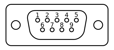
| Pin | Name |
|---|---|
| 1 | UART1 RS-485 + |
| 2 | UART5 RXD |
| 3 | UART5 TXD |
| 4 | CAN0_H |
| 5 | GND |
| 6 | UART1 RS-485 - |
| 7 | UART5 RTS[1] |
| 8 | UART5 CTS[2] |
| 9 | CAN0_L |
- [1]Output only
- [2]Input only
CN6 Barrel Jack
The barrel jack marked CN6 is a center-pin-positive 5.5 mm OD, 2.1 mm ID coaxial power connector. See Specifications section for power input specifications when using this.
Specifications
Specifications
Power Specifications
The TS-7553-V2 accepts a range of voltages from 5 V to 28 V DC. Note that there is a dead zone around 5.4 V as this is the transition point from directly accepting 5 V input to changing over to the switching regulator that can accept up to 28 V. The full voltage range is accepted on the same set of power input pins.
| Input | Min voltage | Max voltage |
|---|---|---|
| 5 V input range | 4.7 | 5.3 |
| 28 V input range | 5.6 | 28 |
Power Consumption
Power consumption of the TS-7553-V2 can vary greatly depending on the build options, the peripherals in use, and the end application behavior. The majority of the power savings are in the automatic CPU scaling and by disabling the Ethernet PHY. Additionally, direct 5 V input is more efficient than using a higher input voltage. This is due to the fact that any input voltage above 5 V is first run through an on-board switching regulator in order to regulate it down to 5 V.
The following tests were performed on a TS-7553-V2 Rev. D PCB with the aftermarket Debian Stretch with Linux kernel 4.9 image. When the measurements were taken the USB serial console was disconnected first to ensure the most accurate measurement possible and the TS-SILO supercapacitors were not charging during the testing. The exact model used for testing is TS-7553-V2-SMW5I. Please see Power Consumption Caveats for details on how to get these power numbers.
TS-7553-V2-SMW5I
| Test | Input (V) | Avg. (W) | Peak (W) |
|---|---|---|---|
| CPU idle, eth0 brought down, booted from SD card, CAN disabled | 5 VDC | 0.385 W | 0.525 W |
| CPU idle, eth0 linked, booted from SD, CAN disabled | 5 VDC | 0.670 W | 0.830 W |
| CPU running openssl speed, eth0 linked running iperf, booted from SD, CAN enabled | 5 VDC | 1.105 W | 1.160 W |
| CPU idle, eth0 brought down, booted from SD card, CAN disabled | 12 VDC | 0.490 W | 0.700 W |
| CPU idle, eth0 linked, booted from SD, CAN disabled | 12 VDC | 0.830 W | 0.970 W |
| CPU running openssl speed, eth0 linked running iperf, booted from SD, CAN enabled | 12 VDC | 1.320 W | 1.355 W |
Power Consumption Caveats
In order to achieve the numbers documented above, there are some operational caveats that must be noted.
- Due to the design of the Ethernet MAC/PHY of the i.MX6UL CPU and the software patterns of U-Boot and the Linux kernel, the PHY is booted to Linux in a high power state. This occurs even though Linux leaves the interface unconfigured and down. This is because U-Boot brings up the MAC and PHY devices to configure them, but leaves them on. Lower power can be achieved by bringing the interface up and then back down if the interface is not in use; the kernel puts the PHY in a low-power state when the interface is brought down. This can be done with:
ifconfig eth0 up
ifconfig eth0 down
- The WILC WiFi device achieves the lowest power if either the kernel module (
wilc_spi) is not loaded, or if thewlan0interface is brought up but left unconfigured. If WiFi/BLE is not needed for an application, it is best to prevent thewilc_spimodule from being loaded. If only BLE is needed in an application, thewlan0interface needs to be brought up first and left active regardless. If WiFi is used in an application, then the driver will automatically handle power levels during operation of the interface.
Supercapacitors
Charging of the supercapacitors causes a change in overall power consumption of the whole system. Because of this, the numbers below are the average curve and peak power draw during a full charge cycle of the TS-SILO technology itself. In other words, the power noted below is separate from the numbers listed above and should be added to the numbers above to sum the total power draw of the whole device.
The current consumption of TS-SILO supercapacitors is not linear during charging. The charge process has a curve to it and the maximum average current consumption is near 80% of full capacity. Below we document the minimum and maximum average over the whole curve and the peak consumption that could be seen.
TS-SILO charging
| Charging V | Min Avg. W | Max Avg. W | Peak W |
|---|---|---|---|
| 5 | 0.85 | 1 | 1.45 |
| 12 | 2.7 | 5.3 | 6.3 |
Backup / Restore
While all of our products ship with images pre-loaded in to any supplied media, there are many situations where new images may need to be written. For example, to restore a device to its factory settings or apply a customized image/filesystem for application deployment. Additionally, specific units may be used for development and that unit's disk images need to be replicated to other units to be deployed in the field.
We offer a number of different ways to accomplish both capturing images to be written to other units, and the actual writing process itself. See the section on our USB Image Replicator tool to capture and/or write images, as well as details on manual processes to capture and write images on each of this device's media.
Software Images
| Revision | Changes |
|---|---|
| ts7553v2-debian-12-bookworm-headless-20250711.tar.xz (md5) ts7553v2-debian-12-bookworm-minimal-20250711.tar.xz (md5) |
|
| ts7553v2-debian-bookworm-headless-20240904.tar.xz (md5) ts7553v2-debian-bookworm-minimal-20240904.tar.xz (md5) |
|